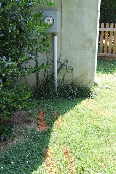
Miss Utility marks underground electric, phone and
cable TV. They do not mark private utilities
such as sprinkler systems, yard lights, etc.
2.
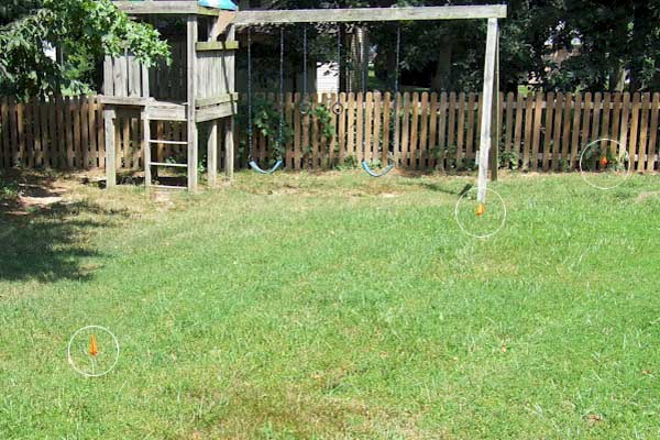
Geothermal wells are located with red flags 10 to 15 ft on center.
3.
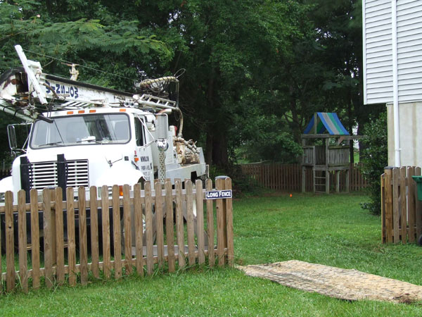
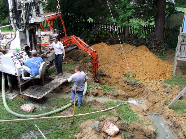
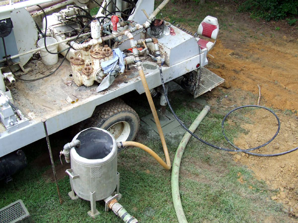
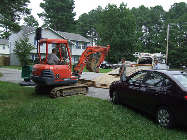
Drill rig moved on site.
4.
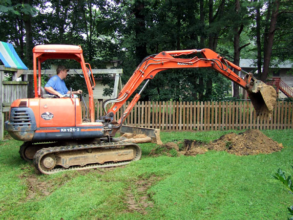
Drill pit dug to hold drilling water and drill cuttings from the geo well.
5.
Drill rig set up over red flag and prepares to drill.
Rig drills a 4" diameter hole 200' in depth, cutting from hole remain in mud pit and water is recycled down the well to bring up more cuttings.
6.
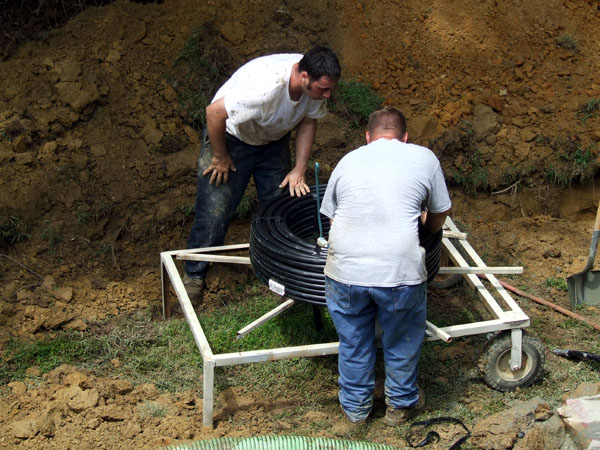
Geothermal loop is placed on the white unreeler and filled with clean water to overcome the buoyancy of the pipe.
7.
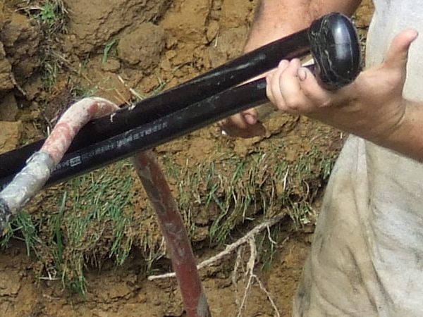
The loop consist of two coils of ¾"polyethylene pipe joined together at one end with 2, 90° fittings called a "U" Bend.
8.
Geo loop is inserted into the well and weight placed on it to keep it in place.
9.
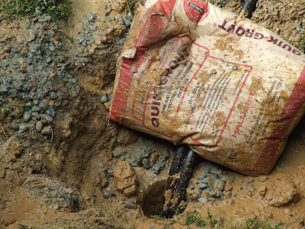
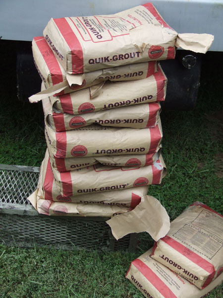
Bentonite grout is used to fill the annular space around the geo loop to allow heat transfer to and from the geo loop.
10.
Bentonite grout and water are placed in mixing tub and pumped under pressure through a 1" high-pressure polyethylene pipe.
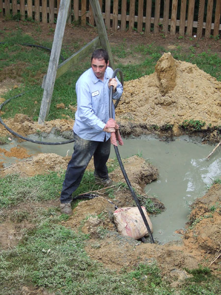
11.
The 1" pipe is place in the geo well and the grout material is pumped from the bottom of the well to the surface.
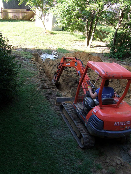
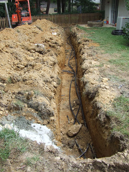
12.
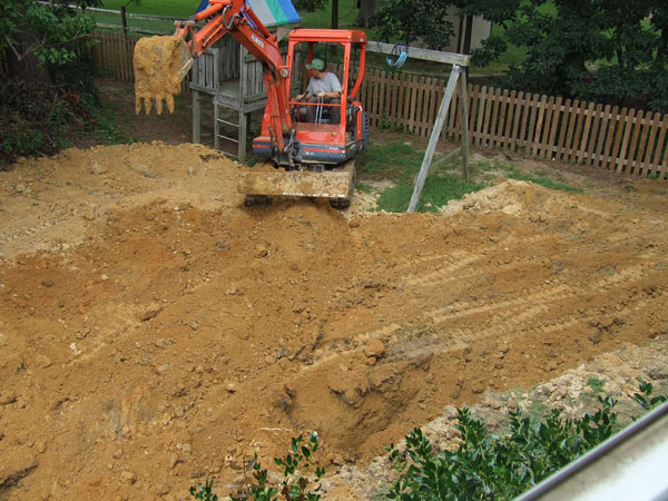
Horizontal trench being dug from geo wells to the home utility room.
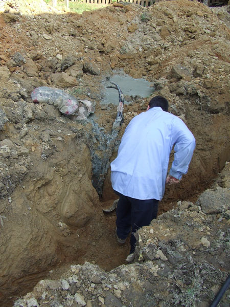
13.
Soil being removed by hand near geo loop to prevent damage by excavator.
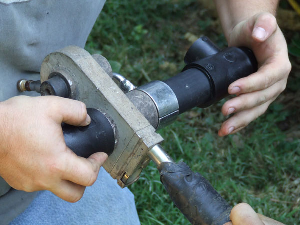
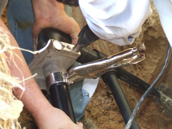
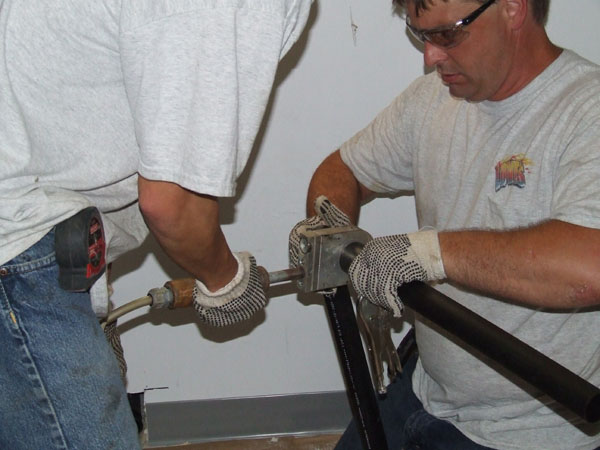
14.
Pipe and fitting being heated to 525° by a heat fusion tool. Tool is then removed and then pipe and fitting are pushed together to make a welded joint.
15.
One pipe of the vertical loop has been fused to the horizontal piping system called a "supply header system." The second vertical loop will then be attached to the "return header system."
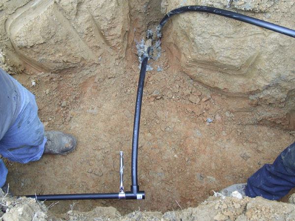
16.
1-¼" supply and return line are placed in the trench.
17.
Supply and return lines are fused to the headers.
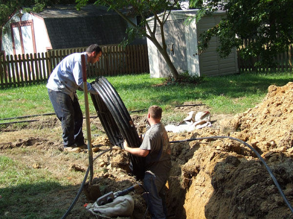
18.
Supply and return lines are uncoiled and placed in trench to the house.
19.
Holes are drilled through the basement wall for the supply and return lines.
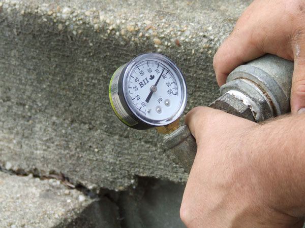
20.
Inground loop field is filled with water and pressurized with air to test the system for leaks.
21.
Supply and return lines are placed through the two holes into the utility room.
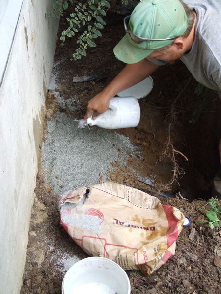
22.
Wall penetration is sealed with waterproof cement and Bentonite grout.
23.
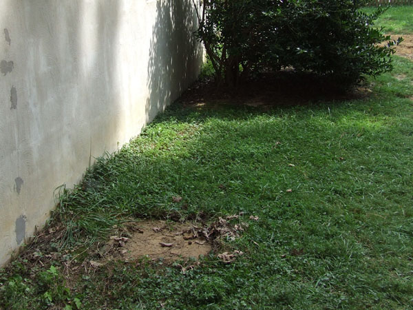
Loop field and trenches are backfilled and leveled.
24.
Excavating equipment is then moved off site and project is turned over to the heating contractors for geothermal unit installation.
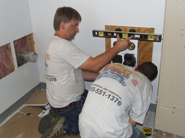
25.
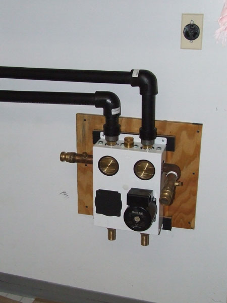
Geo system flow center is mounted on the wall near the geo unit.
26.
Supply and return lines are run from the wall penetration to the geo flow center.
27.
Brass fittings are attached to the flow center to allow fill, flush and purging of the unit and loop field. Brass fittings will be removed when serving is complete.
28.
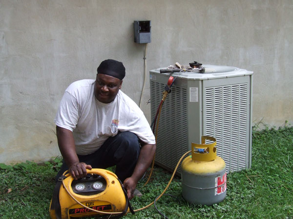
Freon being removed from existing system.
29.
Outdoor condensing unit removed.
30.
Indoor existing system being removed.
31.
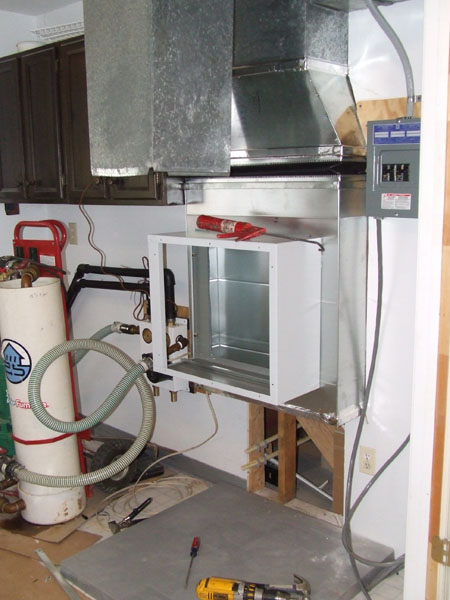
Duct work being installed to fit new geo unit. Serving flush cart is attached to the flow center with two flexible service hoses.
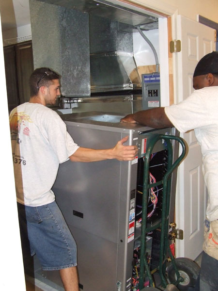
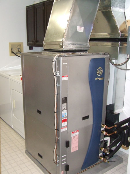
32.
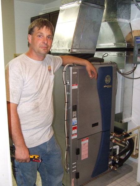
New geo unit being set in place.
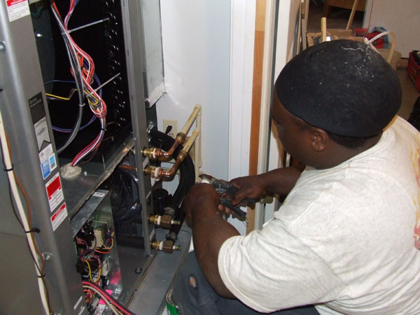
33.
Unit being connected to flow center, hot water heater, 220 volt electric and thermostat wiring.
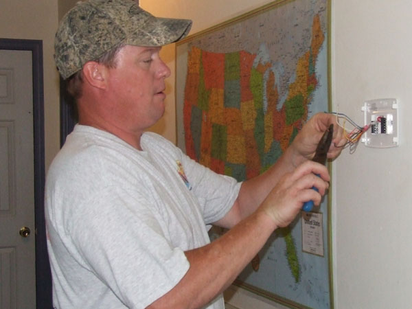
34.
New touch-screen thermostat being installed.
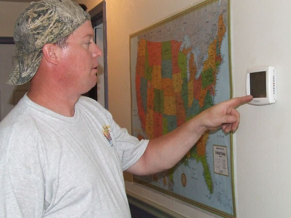
35.
Homeowner being briefed on thermostat functions.
36.
System being inspected and placed in service.
37.
Owner now enjoying the comfort and energy savings for years to come.